
Automotive glass encapsulation brings a large, fragile insert into a molding cell that must control shot size, clamping, material condition, and handling with care. The digital layer must reflect those physical demands.
A rubber injection molding machine for auto glass encapsulation may need to generate dependable records that help production teams coordinate recipes, glass identity, machine states, quality decisions, and maintenance.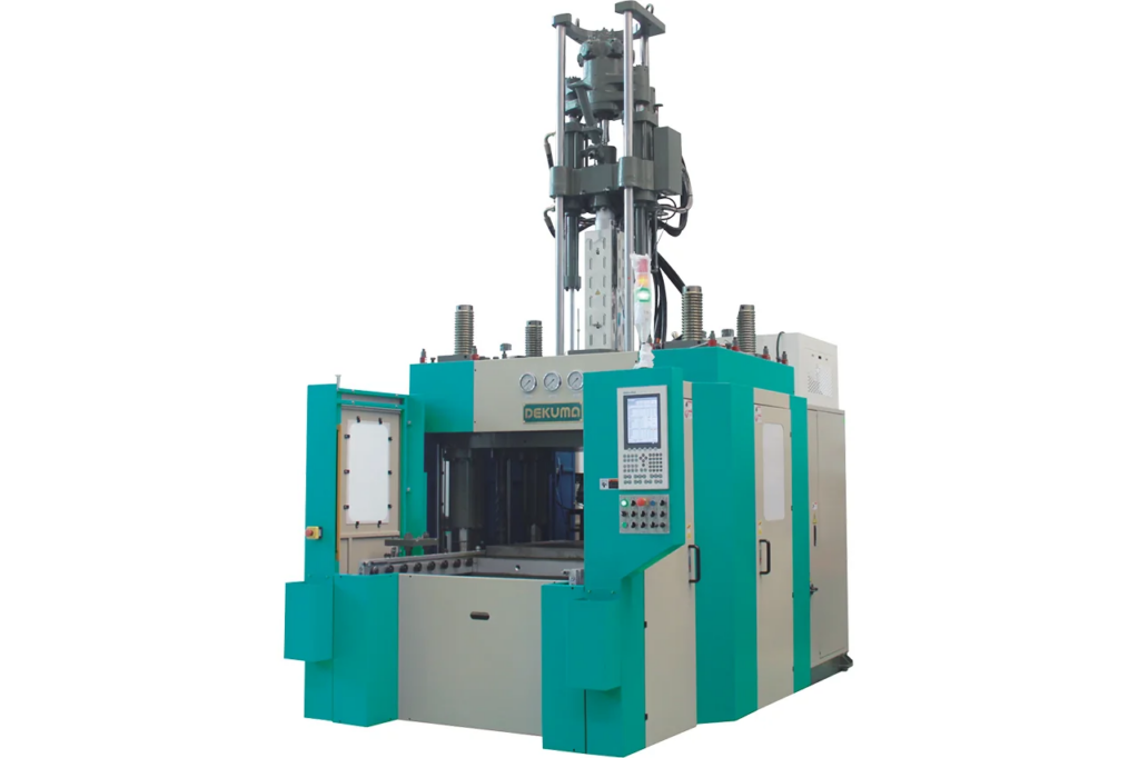
Connect Product Identity to the Molding Recipe
Traceability begins before the glass reaches the press. A production record can link the window type, glass batch or serial identifier, mold, TPV lot, recipe version, work order, and inspection plan.
In glass injection molding, that context is essential because a correct pressure or temperature value means little if it cannot be associated with the part and tooling that produced it. Barcode or other identification systems can reduce manual entry, provided their verification and exception paths are defined.
Machine data will need to be selected for a purpose. Injection volume, pressure, injection rate, platen position, clamping state, material temperature, cycle time, alarms, and operator interventions may support process review. Quality teams may also need confirmation that the correct mold and material were present.
Sampling frequency, engineering units, timestamps, retention periods, and rules for missing readings may need to be agreed before connection so that reports remain consistent after shifts, products, or software versions change. The interface also needs to show whether each value is current, delayed, manually entered, or unavailable.
A communication failure must not leave an old reading displayed as a live normal condition. Recipe revisions and user actions need timestamps and authorization records. Establishing these rules early gives engineering and quality teams a common basis for interpreting data during trials and routine production.
Stabilize the Injection and Clamping Sequence
Our equipment uses a FIFO vertical injection unit that allows material in the injection chamber to be renewed quickly. A patented injection structure combines hydraulic control with a servo-motor pump to improve repeat-shot accuracy.
During glass injection molding, servo output follows the required pressure and flow instead of maintaining unnecessary output throughout the cycle. Energy use can be reduced by up to 60% compared with traditional proportional pressure-and-flow control, although the actual result depends on cycle demand and the comparison baseline.
The fixed lower platen, movable upper platen, and four-column structure distribute clamping force evenly. A low working platform improves access around large windows. These features help create repeatable positions for loading and removal, but automation still requires confirmation of glass placement, mold clearance, guarding, and clamping status.
The control sequence may need to prevent injection when an insert is missing or misaligned and should give trained staff a safe, documented recovery method after an interrupted cycle. Our planning at Dekuma organizes connectivity around the complete one-step TPV encapsulation process.
Match Automation to Large-Window Handling
One-step encapsulation forms the TPV edge seal around the glass rather than molding a strip first and attaching it manually afterward. This can remove handling stages and their associated variation.
The rubber injection molding machine for auto glass encapsulation can also process TPE, flexible modified PVC, and other injection-moldable materials when configured appropriately. Material changes need controlled purging, verified settings, and clear segregation so that a previous compound does not compromise the next production order.
Large windows require automation that supports the part rather than forcing it through a generic take-out path. Robot reach, end-of-arm tooling, glass deflection, locating features, transfer height, and inspection access must be reviewed together.
Cycle studies may need to include loading, confirmation, cleaning, molding, removal, inspection, and rejected-part handling. A device that shortens one movement may not improve output if another station becomes the constraint or if fault recovery takes too long.
Use Model Data to Define a Realistic Interface
Published DKM-RV250B and DKM-RV400B models provide 250- and 400-ton clamping force. Both list 1,840 kg/cm2 injection pressure, 546 cc theoretical injection volume, a 242 cc/s injection rate, 600 mm opening stroke, and 1,000 mm maximum mold-opening distance and sliding stroke.
Platen dimensions differ, at 1,100 x 1,000 mm and 1,250 x 1,100 mm, while approximate machine weights are 13 and 17 tons. Model selection must therefore consider the complete glass and mold envelope rather than clamping force alone.
Pump power is listed at 46.1 kW and electric heating capacity at 13.22 kW. Energy monitoring must separate production, warming, waiting, and fault states and normalize results by acceptable output.
The MES can then reveal whether a higher total is caused by a larger product, longer idle time, recipe drift, or a developing maintenance issue. This is more actionable than comparing daily electricity totals without production context. Commissioning should test the information path with the physical process.
Teams can compare screen values with MES records, introduce a controlled recipe mismatch or identification error, and verify the expected alarm and hold. They may also need to confirm that production remains safe during a network interruption and that delayed records can be reconciled without duplicating parts or losing genealogy.
A connected encapsulation cell improves traceability and operating discipline only if product identification, repeat-shot control, safe handling, and data ownership are defined without shifting time-critical machine functions to the factory network.
We support automotive glass projects with equipment configuration, commissioning, maintenance, and after-sales assistance. Our approach at Dekuma uses smart control as the foundation and MES as the layer that organizes verified events into production knowledge.